Reactor types for power generation
Of the 422 nuclear reactors for power generation worldwide that are in operation or ready for operation, the majority (303) are pressurised water reactors (PWRs). The second largest group is made up of boiling water reactors (BWRs) with 49 plants. Both groups are often referred to as light water reactors because they use light water, i.e. the naturally occurring water consisting of two hydrogen atoms with only one proton and one oxygen atom each, both as a coolant and as a moderator to slow down the neutrons. This deceleration is necessary to maintain a chain reaction with fission of the uranium isotope uranium-235.
Other reactor types in use today are pressurised water reactors with heavy water (D2O, two deuterium atoms and one oxygen atom) for cooling and moderation, of which there are 47 plants. They are mainly designed as pressurised tube reactors (CANDU), but there are also two plants with pressure vessels similar to the PWR. Other plant types include light-water-cooled and graphite-moderated pressurised reactors of the Soviet/Russian RBMK type (11 plants), gas-cooled and graphite-moderated plants of the British AGR type (8 plants), sodium-cooled, unmoderated fast reactors (3 plants) and a gas-cooled, graphite-moderated high-temperature reactor (HTR).
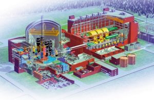
Sectional view (schematic) EPR (Evolutionary Power Reactor); Olkiluoto 3
Nuclear power plant with boiling water reactor
Example: Gundremmingen nuclear power plant unit C
Technical data on the Gundremmingen nuclear power plant unit C
Nuclear fuel UO2/MOX
Fissile fraction of uranium fuel elements (U) 3.13 - 4.6 wt. %
MOX fuel elements (U+Pu) 3.27 - 5.47 wt. %
Nuclear fuel quantity 136 tonnes
Number of fuel assemblies 784
Number of fuel rods per fuel element 80 to 96
Fuel element length 4,470 mm
Number of control rods 193
Absorber material boron and hafnium
Coolant and moderator H2O
Thermal reactor capacity 3,840 MW
Gross electrical output 1,344 MW
Net electrical output 1,288 MW
Gross efficiency 35 %
The fuel elements, which contain the uranium dioxide, are located in the pressurised container, which is about two thirds full of water. The water flows from bottom to top through the reactor core and dissipates the heat generated in the fuel rods. Some of the water vaporises. After steam-water separation in the upper part of the pressure vessel, this saturated steam with a temperature of 286 °C and a pressure of approx. 69.6 bar is fed directly to the turbine. The steam volume is up to 7,477 tonnes of steam per hour.
The turbine is coupled with a three-phase generator that delivers an output of 1,344 megawatts (active power) at a voltage of 27 kV. The frequency is 50 Hz. The water that has not evaporated in the pressure vessel flows back down in the annular space between the pressure vessel and the reactor core, where it mixes with the feed water pumped back from the condenser. The pumps in the pressure vessel circulate the coolant. By changing the speed of these pumps, the circulation rate of the coolant can be changed, thereby controlling the reactor output. At the reactor's rated output, around 51,480 tonnes of coolant flow through its core every hour. The steam escaping from the turbine is liquefied in the condenser. This requires around 160,000 m3 of cooling water per hour, which is cooled via a cooling tower. The feed water is brought to a temperature of 215 °C by preheating systems and fed back into the reactor.
The control rods, which contain the neutron-absorbing material, are retracted into the reactor core from below by electric motor (normal drive) or hydraulically (rapid shutdown) or pulled out again. From the containment vessel, the pipes travelled to the outside of the nacelle. As the steam is not free of radioactive impurities (in particular N16), the nacelle must also be included in a safety shield. In addition, a number of other safety devices are installed to ensure that the steam flow to the nacelle is interrupted immediately in the event of a fault.
The reactor pressure vessel containing the fuel elements is a cylindrical steel vessel. It is shielded with a concrete shield and is located together with a number of other plant components and safety equipment in a containment, which is not shown in the schematic diagram.
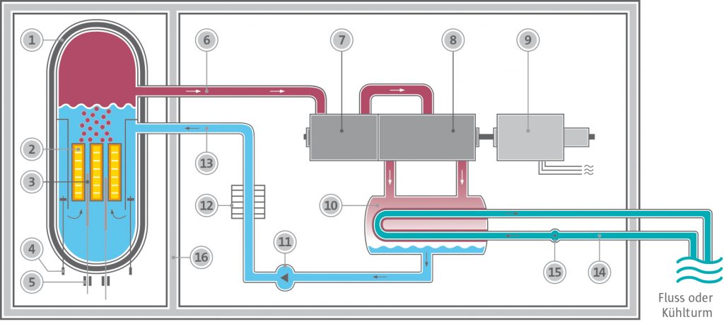
Nuclear power plant with boiling water reactor (simplified schematic drawing)
1 reactor pressure vessel
2 fuel elements
3 control rods
4 Circulation pumps
5 Control rod drives
6 Live steam
7 High-pressure part of the turbine
8 Low-pressure part of the turbine
9 Generator
10 Capacitor
11 Feed water pump
12 Preheating system
13 Feed water
14 Cooling water
15 Cooling water pump
16 Concrete shielding
Nuclear power plant with pressurised water reactor
Example: Brokdorf nuclear power plant
Technical data on the Brokdorf nuclear power plant
Nuclear fuel UO2/MOX
U-235 enrichment up to 4 %
Nuclear fuel quantity 103 tonnes
Number of fuel assemblies 193
Number of fuel rods per fuel element 236
Fuel rod length 4.83 m
Number of control rods 61
Absorber material In, Ag, Cd
Coolant and moderator H2O
Thermal reactor capacity 3,900 MW
Gross electrical output 1,480 MW
Net electrical output 1,410 MW
Gross efficiency 38 %
The reactor pressure vessel containing the fuel elements is a cylindrical steel vessel. It is shielded with a concrete shield and is located together with a number of other plant components and safety equipment in a containment vessel, which is not shown in the schematic diagram. The heat generated in the fuel elements is dissipated through the water. To prevent boiling, the operating pressure in the main cooling circuit is increased to 157 bar and regulated by a pressuriser. The coolant enters the reactor at a temperature of 291 °C and leaves it at a temperature of 326 °C. Around 67,680 tonnes of coolant are moved through the reactor every hour.
The heated water transfers its heat to the water in a secondary circuit in four steam generators (only one of which is shown). Due to the high temperature and low pressure, it evaporates in the secondary circuit and delivers 2.14 tonnes of saturated steam per second at 283.8 °C and a pressure of 67 bar. This dual-circuit system ensures that the radioactive substances present in the reactor coolant remain confined to the first cooling circuit and do not enter the turbine and condenser.
The steam generated is used to operate a turbine (high-pressure section, low-pressure section) that is directly coupled to a three-phase synchronous generator. The generator delivers an output of 1,480 megawatts (active power) at the terminals at a voltage of 27 kV. The frequency is 50 Hz. The vapour escaping from the turbine is liquefied again in the condenser. This requires around 208,000 m3 of cooling water per hour, which is taken from the Elbe. The condensate is fed through a preheating system, preheated to 218 °C and then fed back into the steam generator.
An alloy of silver, indium and cadmium is used as an absorber substance for the control rods of the reactor. For fast control processes, the control rods can be fully or partially inserted into the reactor and removed again. For slow or long-term control processes, boric acid is added to the reactor cooling water as a neutron absorber. The fuel elements are located in a pressurised container made of special steel (wall thickness 25 cm), which is housed in a double-walled containment together with the primary circuit.
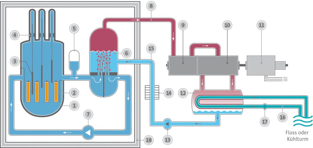
Nuclear power plant with pressurised water reactor (simplified schematic drawing)
1 reactor pressure vessel
2 uranium fuel elements
3 control rods
4 Control rod drives
5 Pressure holder
6 Steam generator
7 Coolant pump
8 Live steam
9 High-pressure part of the turbine
10 Low-pressure part of the turbine
11 Generator
12 Capacitor
13 Feed water pump
14 Preheating system
15 Feed water
16 Cooling water
17 Cooling water pump
18 Concrete shielding
Nuclear power plant with pressurised heavy water reactor (CANDU)
This heavy-water pressure-tube reactor - often referred to as a CANDU reactor (CANada Deuterium Uranium) - is a type of reactor developed by a Canadian company and is mainly used in Canada and India. Two CANDU reactors are also in operation at the Cernavoda nuclear power plant in Romania.
Pressure pipes containing the fuel elements run horizontally through an almost unpressurised moderator tank filled with heavy water (D2O), through which D2O flows as the primary coolant to dissipate the heat generated during nuclear fission. To prevent boiling, this primary coolant is pressurised to around 100 bar. The heated heavy water transfers its heat in steam generators to the secondary circuit, in which water - H2O - vaporises and drives the generator via a turbine.
By using D2O as a moderator, it is in principle possible to use natural uranium, i.e. uranium with a natural content of only around 0.7 % of the fissile isotope uranium-235. However, uranium enriched to up to 2 % of U-235 is usually used today. The use of pressurised tubes instead of a large-volume pressure vessel as in pressurised water reactors leads to technically simpler production.
This also makes it possible to change the fuel elements during reactor operation by switching off individual pressure tubes in order to change the fuel elements.
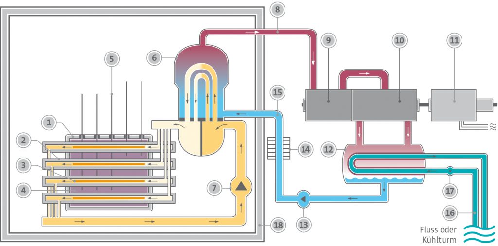
Nuclear power plant with pressurised heavy water reactor (CANDU) (simplified schematic drawing)
1 moderator tank
2 pressure tubes
3 Uranium fuel elements
4 Heavy water moderator
5 control rods
6 Steam generator
7 Coolant pumps
8 Live steam
9 High-pressure part of the turbine
10 Low-pressure part of the turbine
11 Generator
12 Capacitor
13 Feed water pump
14 Preheating system
15 Feed water
16 Cooling water
17 Cooling water pump
18 Concrete shielding
Nuclear power plant with graphite-moderated pressurised boiling water reactor (RBMK)
RBMK is the abbreviation of the Russian name for a graphite-moderated, water-cooled, pressurised boiling water reactor. The reactor core consists of around 1,700 tonnes of graphite bricks, which are stacked to form a cylindrical block 7 m high and 12 m in diameter. The volume of the reactor core is more than 10 times larger than that of a typical boiling water reactor.
There are vertical holes in the graphite block for the 1,693 pressure tubes, each of which contains a fuel element with two fuel rod bundles arranged one behind the other, each consisting of 18 fuel rods. Each fuel rod bundle is 3.65 m long and contains 64.8 kg of uranium dioxide with a proportion of 2.4 % U-235. In total, the reactor contains around 193 tonnes of uranium. Further boreholes in the graphite block contain the 191 control and shutdown rods.
The heat generated in the fuel elements by nuclear fission is absorbed by the surrounding water in the pressure tubes, which partially vaporises as a result. The water-steam mixture passes from the pressure tubes to steam separators, where the water and steam are separated. The steam flows to two turbines and the water is pumped back into the reactor.
The advantages of this type of reactor developed in the former USSR lay in
- the simpler production of pressure tubes compared to large-volume pressure vessels,
- the easier development of larger capacity reactors, as the number of similar components only needed to be increased,
- fuel element replacement during plant operation without downtimes.
A serious disadvantage is that positive reactivity feedback can lead to an uncontrolled power excursion, as there is no inherent self-stabilisation when temperatures rise above the design limits, as is the case with pressurised and boiling water reactors. This characteristic, among others, led to the Chernobyl accident.
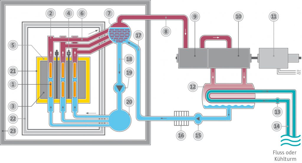
Nuclear power plant with graphite-moderated pressurised boiling water reactor (RBMK) (simplified schematic drawing)
1 Uranium fuel elements
2 Fuel element pressure tube
3 Graphite moderator
4 control rods
5 Shielding gas (N2/He)
6 Steam/water
7 Vapour separator
8 Steam to the turbine
9 High-pressure section of the steam turbine
10 Low-pressure section of the steam turbine
11 Generator
12 Capacitor
13 Cooling water pump
14 Cooling water
15 Feed water pump
16 Preheating system
17 Condensate (water)
18 Water return
19 Circulation pump
20 Water distributor
21 Steel reactor vessel
22 Concrete shielding
23 Reactor building
Nuclear power plant with graphite-moderated gas-cooled reactor (AGR)
The AGR - Advanced Gas-cooled Reactor - is a graphite-moderated, CO2-cooled reactor built and operated in the UK. It is a further development of the reactor type with which the world's first commercial nuclear power plant - Calder Hall, England - supplied electricity to the public grid on 27 August 1956. Uranium enriched to up to 2.7 % is used in the AGR. The temperature of the CO2 coolant is around 650 °C and the water vapour temperature at the turbine inlet is 566 °C. This enables the plant to achieve a high efficiency of 41.6 %.
However, this advantage is offset by the disadvantage that the utilisation of the uranium fuel (the so-called burn-up) is significantly lower than in pressurised and boiling water reactors.
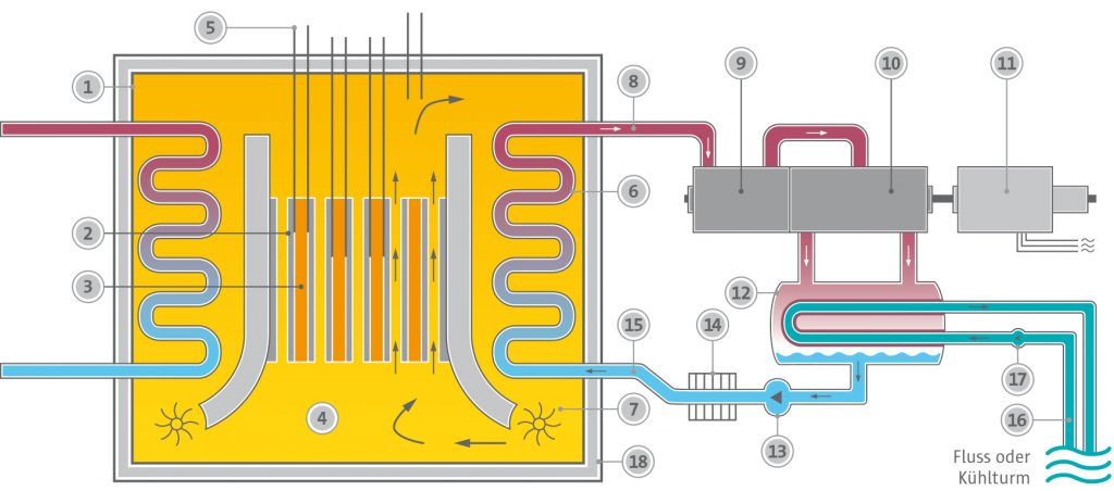
Nuclear power plant with graphite-moderated gas-cooled reactor (AGR) (simplified schematic drawing)
1 Uranium fuel elements
2 Fuel element pressure tube
3 Graphite moderator
4 control rods
5 Shielding gas (N2/He)
6 Steam/water
7 Vapour separator
8 Steam to the turbine
9 High-pressure section of the steam turbine
10 Low pressure part
of the steam turbine
11 Generator
12 Capacitor
13 Cooling water pump
14 Cooling water
15 Feed water pump
16 Preheating system
17 Condensate (water)
18 Water return
19 Circulation pump
20 Water distributor
21 Steel reactor vessel
22 Concrete shielding
23 Reactor building
Nuclear power plant with high-temperature reactor
While light water reactors achieve coolant temperatures of up to around 330 °C, the coolant temperature in high-temperature reactors is 750 °C and above. This means that not only steam can be generated to drive turbines, but also process heat, e.g. for coal gasification or to produce hydrogen.
Two experimental power plants with high-temperature reactors were operated in Germany in order to gain technical experience. The fuel elements in these high-temperature reactors were graphite spheres with a diameter of 6 cm. They contained about 1 g of uranium-235 as fissile material and 10 g of thorium-232 as breeding material. The chain reaction is maintained by the fission of uranium-235. Some of the neutrons released during fission are captured by Th-232. The resulting Th-233 decays into protactinium-233, from which further beta decay produces U-233, which can also be fissioned by slow neutrons. During operation, this reactor therefore produced part of the fissile material itself.
Graphite was used as the moderator. The heat generated in the reactor was conducted to the outside by helium heated up to 750 °C. In steam generators, the helium transferred its heat to a water-steam cycle. In steam generators, the helium gave off its heat to a water-steam cycle.
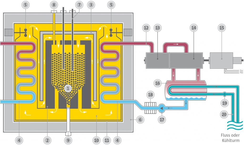
Nuclear power plant with gas-cooled high-temperature reactor (simplified schematic drawing)
1 reactor core (pebble bed)
2 Neutron reflector (graphite)
3 Iron shield
4 Steam generators
5 Cooling gas fan
6 Prestressed concrete container
7 Control rods
8 Ball pull rennet tube
9 Ball trigger tube
10 Cooling gas (helium)
11 Steel sealing skin
12 Live steam
13 High-pressure part of the turbine
14 Low-pressure part of the turbine
15 Generator
16 Capacitor
17 Feed water pump
18 Preheating system
19 Cooling water pump
20 Cooling water
Nuclear power plant with fast reactor
In boiling and pressurised water reactors, only U-235 can be split from the uranium isotopes found in nature. However, the process can be controlled in a special type of reactor so that U-238 is also utilised. U-238 absorbs a neutron and U-239 is produced, which is converted into fissile Pu-239 via neptunium-239. This process allows more fissile material to be produced than is consumed by nuclear fission for reactor operation. As fast neutrons are used for the process in such a reactor, this type of reactor is called a "fast reactor" or "fast breeder reactor" due to the possibility of gaining fissile material.
As such reactors can only be operated with fast neutrons, there must be no moderator. Water is therefore unsuitable as a coolant, as it slows down (moderates) the neutrons to low speeds. Liquid sodium, for example, is therefore used as a coolant. Its melting point is 98 °C and its boiling point is 883 °C. In the reactor core, the sodium coolant is heated to around 550 °C.
As the sodium does not boil, the resulting pressure is also relatively low. In the primary circuit, it is around 10 bar. The sodium that flows through the reactor core becomes radioactive due to the neutron radiation. For safety reasons, the sodium in the primary circuit transfers its heat to the sodium in a secondary circuit in a heat exchanger. The sodium in this secondary circuit is then no longer radioactive. Finally, in the steam generator of the third, water-steam cycle, water vapour of around 500 °C is generated and fed to a steam turbine.
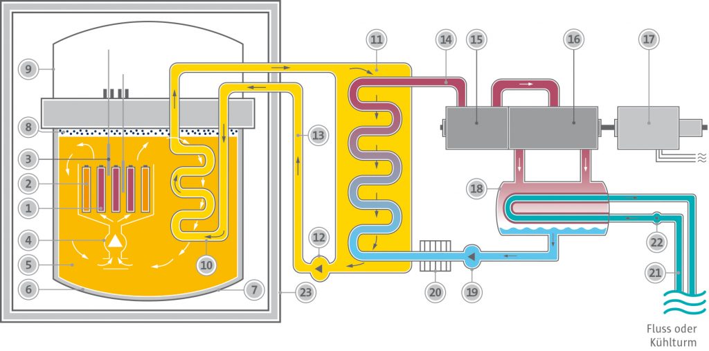
Nuclear power plant with sodium-cooled fast reactor (simplified schematic drawing)
1 fuel element (fission zone)
2 fuel elements (incubation zone)
3 control rods
4 Primary sodium pump
5 Primary sodium for primary sodium circuit
6 Reactor tank
7 Safety tank
8 Inert gas atmosphere (argon)
9 Reactor dome
10 Intermediate heat exchanger
11 Steam generator
12 Secondary sodium pump
13 Secondary sodium circuit
14 Live steam
15 High-pressure part of the turbine
16 Low-pressure part of the turbine
17 Generator
18 Capacitor
19 Feed water pump
20 Preheating system
21 Cooling water
22 Cooling water pump
23 Reactor building